Logo Design by FlamingText.com

Sunday, 15 May 2016

Free energy device .... sans wires


So for the last 3 years I have browsed youtube and seen many vids claiming generate free energy etc. I will admit I did try to construct a few.


Anyways I always stumbled apon the wireless led coils and I was all intrigued.
So today I finally did it and got it working..... sooo happy.


Skill: newb
Time: 1 hr
Materials:
-18 ft 18 guage magnetic wire
-led
- electrical tape
- breadboard
- bc557 transistor
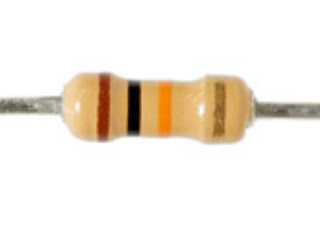
- 47k resistor

Here's how you can build one yourself


Coil A


Make a coil with 9ft magnetic wire with diameter 2cm.

When you get halfway done stop.

Make a loop and twist it down this will be used as a tap. Continue coil till the remaining half is used.


With this transistor  the pin out is CBE


1.Add resistor to base and connect to one end of coil.
2. The other end of coil goes to the  COLLECTOR.
3. Add 1.5 v battery. Positive connects to the    tap. Negative goes to EMITTER


Coil B :


1. Leave 3cm excess and start another coil same size without the tap this time.
2. When finished use tape to secure coil.
3. Add led by attaching anode to one end of coil and the cathode to the other.
Easy peasy

Friday, 13 May 2016

Arduino Robot Chasis Kit

Arduino Robot Chasis

If you don't have one of these then put down everything your doing and hit up this site


                                              http://www.amazon.ca/dp/B00WWGQ5W2

After tinkering around with my arduino I took the pludge and decided to build the avoidance robot. First step was to buy the chasis. I did make one orginally but it was shit and for 20$ why wouldnt I just buy the set.

I ordered from amazon and as always the package arrived sooner then I had thought.
This kit comes with everything you need to get started. 

I highly recommend this product if you are new to arduino not only is it a awesome addition to your bag of toys but it get you started in the world of robotics.


Features

  • Ideal for DIY
  • Mechanical structure is simple, it is easy to install
  • This car is the tachometer encoder
  • With a 4 AA battery box and power switch (batteries not included)

Feature: 

Smart car chassis tracing car Robot car chassis with code disk 
Ideal for DIY 
Mechanical structure is simple- it is easy to install 
This car is the tachometer encoder 
With a 4 AA battery box and power switch (batteries not included) 
Can be used for distance measurement- velocity 
Can use with other devices to realize function of tracing- obstacle avoidance- distance testing- speed testing- wireless remote control 
Size: 20 x 14cm (L x W) 
Wheel size: 6.5 x 2.7cm (Dia. x H) 

Note: 

Motor power supply is 3V ~ 6V. All the parameter above is tested without load. 
The car Chassis is transparent- you need to tear out protective paper. 

Package included: 

1 x Car chassis 
2 x Gear motor 
2 x Car tire 
2 x Speed encoder 
2 x Fastener 
1 x Universal wheel 
1 x Screwdriver 
1 x Battery box(batteries not included) 
All necessary screw and nut


Thursday, 12 May 2016

LED Chaser

Another cool arduino based led project to get ya going. This project is super cool to show off and easy to build.


Skill Level:  Newb

Time: 30 min

Parts Required:
- Breadboard
- Arduino
- 8 Leds
- 8 10k resistors
- Jumper wires
- 10k potentiometer


This is an LED Chaser program with Speed Control
// 8 LED's are connected to the 8 Pins of Arduino
// with a series resistor with each LED
// Potentiometer is Connected to Analog Input pin A0
// refer circuit diagram for reference
// You can Change chaser speed by varying the pot
int led1 = 1;
int led2 = 2;
int led3 = 3;
int led4 = 4;
int led5 = 5;
int led6 = 6;
int led7 = 7;
int led8 = 8;
int count = 1;

void setup()
{
  // put your setup code here, to run once:
  pinMode(1,OUTPUT);
  pinMode(2,OUTPUT);
  pinMode(3,OUTPUT);
  pinMode(4,OUTPUT);
  pinMode(5,OUTPUT);
  pinMode(6,OUTPUT);
  pinMode(7,OUTPUT);
  pinMode(8,OUTPUT);
}

void loop()
{
// i reads the analog pot value connected to A0 pin
// this value changes from 0  - 1023 giving us a delay of
// 0 to 1023 milliseconds
// count variable carries the number of LED pin
// we reset the count to 1 when it becomes more than 8
// because we have only 8 leds connected
  int i =  (A0);
  digitalWrite(count,HIGH); delay(i);
  digitalWrite(count,LOW); delay(i);
  count++;
  if(count > 8)
  {
    count = 1;
  }
}
Thanks guys more to come.....

Arduino LED fade


So now you wanna fade these leds eh
Well let me help ya out.


This is a fairly simple project to get you working with arduino.


Skill level: Begginer
Time: 10 mins
Parts Required:
- Arduino and laptop or pc to connect and upload sketch
- Breadboard
- Jumper wires
- led
- 10k resistor


Here is a code you can run through your arduino to get yer led fading.


Upload this to your sketch
/*
 Fade
 This example shows how to fade an LED on pin 9
 using the analogWrite() function.
 The analogWrite() function uses PWM, so if
 you want to change the pin you're using, be
 sure to use another PWM capable pin. On most
 Arduino, the PWM pins are identified with
 a "~" sign, like ~3, ~5, ~6, ~9, ~10 and ~11.
 This example code is in the public domain.
 */
int led = 9;           // the PWM pin the LED is attached to
int brightness = 0;    // how bright the LED is
int fadeAmount = 5;    // how many points to fade the LED by
// the setup routine runs once when you press reset:
void setup() {
  // declare pin 9 to be an output:
  pinMode(led, OUTPUT);
}
// the loop routine runs over and over again forever:
void loop() {
  // set the brightness of pin 9:
  analogWrite(led, brightness);
  // change the brightness for next time through the loop:
  brightness = brightness + fadeAmount;
  // reverse the direction of the fading at the ends of the fade:
  if (brightness == 0 || brightness == 255) {
    fadeAmount = -fadeAmount ;
  }
  // wait for 30 milliseconds to see the dimming effect
  delay(30);
}

Light that led up


So you wanna light up some leds do ya.

Well in these post I will show ya how to get on your way to some electronic madness.


Difficulty: Newb
Time: 10 mins
Skill: 0
Parts list:

- LED or more
- 10k resistor
- Jumper wires
- Bread board
- 9volt battery with connector


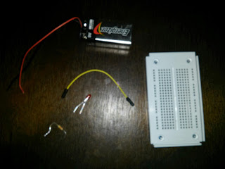
First step gather all of your materials. Hopefully by now you have aquired the proper tools and parts.

Here's the breadboard mine came from the arduino kit I purchased from Amazon.

Some jumper wires. Always a good investment unless of course you make your own like I did with the help of www.we-online.com

As well as a power source I am using from and for a 9v battery.

Now that you have everything let's get started.

Like I said its simple. Place positive end of battery on one breadboard rail. The negative on the other rail. Place led.
Now with the jumpers atach one end to led and one end to the positive rail. Next a jumper from led to negative rail.
In this photo I used a resistor you can also if you have one.


Very simple to add another led same thing as long as the positve goes to positive rail and negative to the negative rail. 

6 in 1 Solar Kit


So lemme just start off by saying this cost only $1 buckaroo so right off the hop its a no brainer to grab.
Me myself actually purchased around twelve of them if you would believe. Why you ask? 

Solar cells and mini motors


The kit comes with everything you need.

Super simple to assemble and these little motors off so many other possiblities.
Snap the plastic pieces together 
Even though it is quite basic it does offer insight on other builds and uses for the parts.
The quality is actually not too shabby considering like I mentioned $1


Here's the best part included in the kit. The solar cell. This cell reports to be 1.5 volt ... thus why I bought 12.
The base just snaps together and then you run the wires
Even the stand offers many uses. It is pretty cool for a small project.
Done and done. I actually used all the solar cells and wired them in series and was reaching around 9v so it was a pretty good investment.

Tuesday, 10 May 2016

Arduino shields part 2

Piezo buzzer shield

"Piezozzers use the inverse piezoelectric principle to create movement of a ceramic disc to produce sound waves. The buzzer includes a built-in oscillating circuit. Piezo buzzers operate over a wide temperature range and create noises ranging from soft and gentle to loud and aggressive."


Sure you could buy a shield but wheres the fun there.
This is a cool addition to your now growing collection.


Okay let's go..

Parts needed : 


PCB Board

Resistor


Header Pins


Once you have all materials get er going.

This is super simple:


 place the buzzer on the pcb ( the example I know is a breadboard... but it at least shows ya) 

Connect postive end of buzzer to.resistor and from there to a header pin.

Connect negative end of buzzer to header pin.


Tapped out hack


Super simple way to hack tapped out and get as many donuts ya want. First off download sb game hacker. If you don't know what that is check out my post on it. Once you have then open tapped out.


Okay so notice how I have 4 donuts. Input 4 or whatever you have to the sb app and click.search.

Ok so itll show you what it found. Usually you have to do this.intil you get a search result under 10 results.


So spend a donut or two to.change the number and then reopen sb hacker.


And repeat

Keep.going like I.said intil your search results are under ten
See there we go now we found the values we wanna change. So type in say 999999 and hit.modify

9999999 cuZ im a baller like that
To activate it now go spend a donut...


Do you love me yet?