Hey there, so after scouring google and forums alike I finally found a circuit I could easily construct with the parts on hand. First off I was skeptical at first that I would see results, but I did! So as of now I am still playing around with the configurations and such. So you may ask what the hell is this that I am looking at.
Well I will explain my intentions, basically I am trying to capture energy from the air and turn it into something usable. With this circuit I draw in RF from my antenna and through this circuit which charges a capacitor, which in turn stores the energy until I discharge it.
So I have been playing around with this circuit for quite some time and I will update this blog when I sit down and do time studies on the effectiveness of the circuit, but to keep it short and sweet my quick answer is yes it does work and I am able to not only charge the capacitor but I am also able to power a 5volt led.
How Does This Work?
This is the circuit I have used for this build,I am unsure of its name, but I do believe it is a Tesla patent
combined with a "Joule Thief", The positive and negative connections of joule thief connect to the positive n negative on the "Tesla" circuit.
Results?:
So far I am capable of charging the capacitor and lighting this led. It is briefly but it is proof of concept for small scale applications. With my lack of parts or even knowledge this will be something I research a little more. With a better antenna and bigger capacitors or even supercapitors I believe I will be able to produce greater results.
I can say roughly in say 2hrs I can flash a 5 volt led
Any ideas or suggestions are greatly appreciated, I would like to learn more about super capacitors and the capabilities.
Hey there, just a quick little snippet of a cool coil and its abilities. This is fairly simple to build and really cool to play around with. The coil is being powered by a 1.5 volt battery and can go upwards of 9 volts..... 12volts and things start smoking lol, make sure you use appropriate resistors
This was a super simple build, which me and my lil guy threw together on a past weekend, it runs off an arduino which is then powered by a 9 volt battery, Eight different coloured leds were used as well as eight glue sticks to add in the cool effects. As well I have added a 10k pot which allows adjustment for the speed of flash.
Code: The sketch is very simple you can either just google it, write it, or just copy and paste you lazy bastard u.
// 8 LED's are connected to the 8 Pins of Arduino
// with a series resistor with each LED
// Potentiometer is Connected to Analog Input pin A0
// refer circuit diagram for reference
// You can Change chaser speed by varying the pot
int led1 = 1;
int led2 = 2;
int led3 = 3;
int led4 = 4;
int led5 = 8;
int led6 = 9;
int led7 = 10;
int led8 = 11;
int count = 1;
void setup()
{
// put your setup code here, to run once:
pinMode(1,OUTPUT);
pinMode(2,OUTPUT);
pinMode(3,OUTPUT);
pinMode(4,OUTPUT);
pinMode(5,OUTPUT);
pinMode(6,OUTPUT);
pinMode(7,OUTPUT);
pinMode(8,OUTPUT);
}
void loop()
{
// i reads the analog pot value connected to A0 pin
// this value changes from 0 - 1023 giving us a delay of
// 0 to 1023 milliseconds
// count variable carries the number of LED pin
// we reset the count to 1 when it becomes more than 8
A joule thief is a self-oscillating voltage booster that is small, low-cost, and easy to build, typically used for driving small loads. This circuit is also known by other names such as joule ringer or blocking oscillator.
It can use nearly all of the energy in a single-cell electric battery, even far below the voltage where other circuits consider the battery fully discharged (or "dead"); hence the name, which suggests the notion that the circuit is stealing energy or "joules" from the source. The term is a pun on the expression "jewel thief": one who steals jewelry or gemstones.
The circuit is a variant of theblocking oscillatorthat forms an unregulated voltage boost converter. The output voltage is increased at the expense of higher current draw on the input, but the integrated (average) current of the output is lowered and brightness of a luminescence decreased.
I have been playing around with this circuit for quite some time and I am very interested in it's applications, it is very simple to build and quite pleasant to watch the results.
Follow these instructions in order to build your own version, later on I will show you some cool experiments I have been working on, using a joule thief plus crystal radio, as well as a joule thief combined with another cool circuit that for the life of me I forget the name, but I came across it while researching Tesla cosmic energy collector. Basically this circuit allows current to be collected from an antenna and it runs forward using diodes and is ran into a capacitor which stores the charge. I have been quite successful in lighting leds.
DIY: Arduino Uno 8x8 Led Chaser
So this weekend I was bored and I am still awaiting some led strips to hopefully be delivered anytime soon......... So I decided to play around with some odd leds I had laying around. As you can also tell the leds are entombed in pinpong balls. This was from a previous build. I do find that using the pingpong balls it does intensify the effect.What I did was cut off the leds at 8 and I did so 8 times. The beauty was these were dollar store leds and they already had resistors and everything done for me. So this was simple. Anyways I loaded up a led chaser sketch and connected each positive end from the leds and connected in the appropriate pins. Easy peasy. It is pretty cool to watch and it sure lights up my room.
If you are looking for a straight forward instruction on how to get this project up and going then keep reading, By the end of this walk through you will have your own Arduino Oscilloscope. Included will be the necessarylibraries as well as the sketch. A big big shout out goes to my new buddy Dani Ardianto.
STEP 1: Gather Materials
The hardware for this project is extremely simple to construct, you will only need an Arduino Uno, as well as a LCD shield. The shield I have used and finally had success with was obtained from ebay and was rather inexpensive. This shield is really cool and simple to use and as a bonus it comes with an SD slot which allows you to be able to display pictures. This is simple to plug into the Arduino and away you go.
As you can see from the picture on the left the pins are clearly defined which makes life a tad easier. As well as the pinouts you can see the website listed: http://www.mcufriend.com. I would recommend if you are have issues that you google that phrase and find your solutions there.
Next you will need your trusty old Arduino Uno, which I hope does not need an introduction. If so then refer to my Arduino posts which cover all aspect from buying to using.
STEP #2: Connect The Hardware
Well this step is super easy. simply connect the shield onto the Arduino by aligning the pins and squeezing it together. Easy peasy.
STEP #3: Software & Libraries
After you have connected your Arduino to your computer you now will need to access Arduino. For this Oscilloscope I had a hell of a time finding the correct library to work. Some worked halfway some libraries did not work at all. Not only did I create a mess downloading tons of libraries but the aftermath of all those files further made life difficult. So if your having issues first off check that your libraries are the right ones as well as placed correctly. ** This may apply to you** The LCD shields contain different ID chips which was why mine never was able to quickly work like those I seen on youtube and such. Believe you me I downloaded smoke and wires too many times to count. So follow this exactly and you will have success.
After you have successfully installed the library and compiled and upload the sketch unto the Arduino you are now on your way to some fun. To use the Oscilloscope you will now need to create a probe or for the time being you can do this.
Connect a RED jumper or wire to the A05 pin on the Arduino. This is used to test.
Connect a Black jumper or wire to the Ground to ground.
That's it. As always enjoy and look back for the next project: DIY Oscilloscope Probe
In this quick lesson we will go over a very simple hook up in order to make an LED of your choice shed some light. In order to do this we will need to gather a few key elements in order to get this project off the ground. Leds can be used for anything and everything, they are perfect to add accents and lighting to your home, car or anywhere else. Nowadays people have shifted focus on using led strip lighting which offers easy installation as well as being easy to control. By following this walkthrough you should be able to understand the setup as well as the concept, so get ready and keep reading.
STEP 1: Gather your gear
For this project you will need:
- L.E.D ( Light emitting diode )
- 220 ohm resistor
- Breadboard
- jumper wires
Light Emitting Diode (L.E.D)
LED
When placing the led onto the breadboard you need to know the orientation of the led itself. Take a look at the led description and get familiar with the different functions. The led in this case has two legs. The longer leg is called an "Anode" this leg is defined as positive (+). This is generally connected to the positive power supply. The shorter leg called an "Cathode" is defined as being the negative pin, which is connected to the ground through a resistor which we will discuss next.
Resistor
Resistors can be used in many different ways, they are mainly responsible for protecting components from being damaged such as in leds. They are the dams of electricity, different resistors can allow different flows to pass through. Resistors can split voltage between parts of a circuit as well as control delays. Most resistors nowadays are carbon. Resistors have values assigned which are rated by the colours on them. The colours used are : black, brown, red, orange, yellow, green, blue,purple, gray, and white. The colours represent a different number. Black = 0 Brown= 1 all the way to White = 9. Remember these numbers you will need to learn which applies to which.
STEP 2: Connections
First things first connect your power supply. I chose as always my own created "PSU" Connect 5v to positive rail on the breadboard (red +) and ground will be connected to the blue breadboard rail (ground). Next insert the led (colour of your choice) into the breadboard as shown in the picture. For more information on how to use a breadboard you can check out my walk through which you will find in my project listings. Place "Anode" in one opening and "Cathode" in its own hole.
Now that the led and the power supply are connected we now move onto connecting the resistor. To do this we need to place the resistor with one end connected to the same rail as the cathode of the led. The other end of the resistor is in its own hole as well. Now place your jumper wires.
Connect the resistor with your jumper wire. One end of the jumper wire will be connected to the cathode end with the other end connected to the ground rail of the breadboard. Now we need power.
To do this we connect another jumper. This wire is connected to the anode of the led. This wire now gets connected to the red rail which will provide the 5v power needed to run the led.
Beautiful eh, if everything went smoothly then you should be sitting back relaxing and enjoying your progress. Some common issues if you cannot make light would be:
After weeks of research and planning as well as waiting for all the parts to be shipped I finally built and finished this amazing project. The aim was to build a power supply without spending a dime... ya that's right this build was free. After quite some time of tinkering with arduino and breadboarding electronics I was getting really annoyed at the lack of options for power and the hassle of unhooking and limited build because of power issues. I then stumbled apon many different versions of the bench top power supply. I noticed however that none of these builds seemed specific for what I was looking for so away I went. I would like to thank all of the suppliers who worked with me and provided the materials needed for this project. Links as well as resources will be included for your own needs.
This power supply is quite handy for many functions. Mine includes three seperate binding posts for different ranges of power such as: +3.3v, +5v, +12v as well as options to expand. Which will be updated as I progress and addon. The cool part of this I believe is in the enclosure itself as it acts as a perfect surface to breadboard as well as operate an ARDUINO or ARDUINO'S lol like I plan.
This project is very easy to do and once built it will allow a cleaner look as well as endless possibilities. Materials:
- ATX power supply:To provide the power
You can salvage one from an old pc like I did plus you can score extra goodies from dismantling a pc
- Enclosure or box or whatever you plan to use: To enclose your project
I used a enclosure from OKW ENCLOSURES INC. These guys can help out with custom enclosures of all sorts. You can check them out @ http://www.okusa.com/
- Binding Posts:Used for connecting
I lucked out and found a great supplier CHK ELECTRONICS who was eager to help and provided sweet binding posts you can check out the site @ http://www.chk-electronics.com/home.php
- Leds:Used to display standby mode as well as power good mode
I scored yet again and found a great site and company BIVAR LED who was willing to help a brother out you can check it out @ http://www.bivar.com/
- Resistors: I used two 300ohm resistors each one attached to the negative leg of each led. It was all I had in my tackle box
- 12v pc fan: Acts in place of minimum load required to operate atx
I didnt have a 10w sandbar resistor so I figured if the atx needs something to draw minimum current why not just use a fan. This way it doubles as a cooling unit as well as provides the resistance... I could be wrong but it made sense to me.
Salvaged from the pc I killed
- Illuminated Push button: Serves as an on/off
I chose to use an illuminated button for two reasons. One, it looks mint and as well provides a good function to be able to turn source on and off. I was lucky to get a supplier NKK SWITCHES who helps out quite often with my projects. They have a ton of product at great prices. You can check em out @ http://www.nkkswitches.com/products/illuminated-pushbutton/
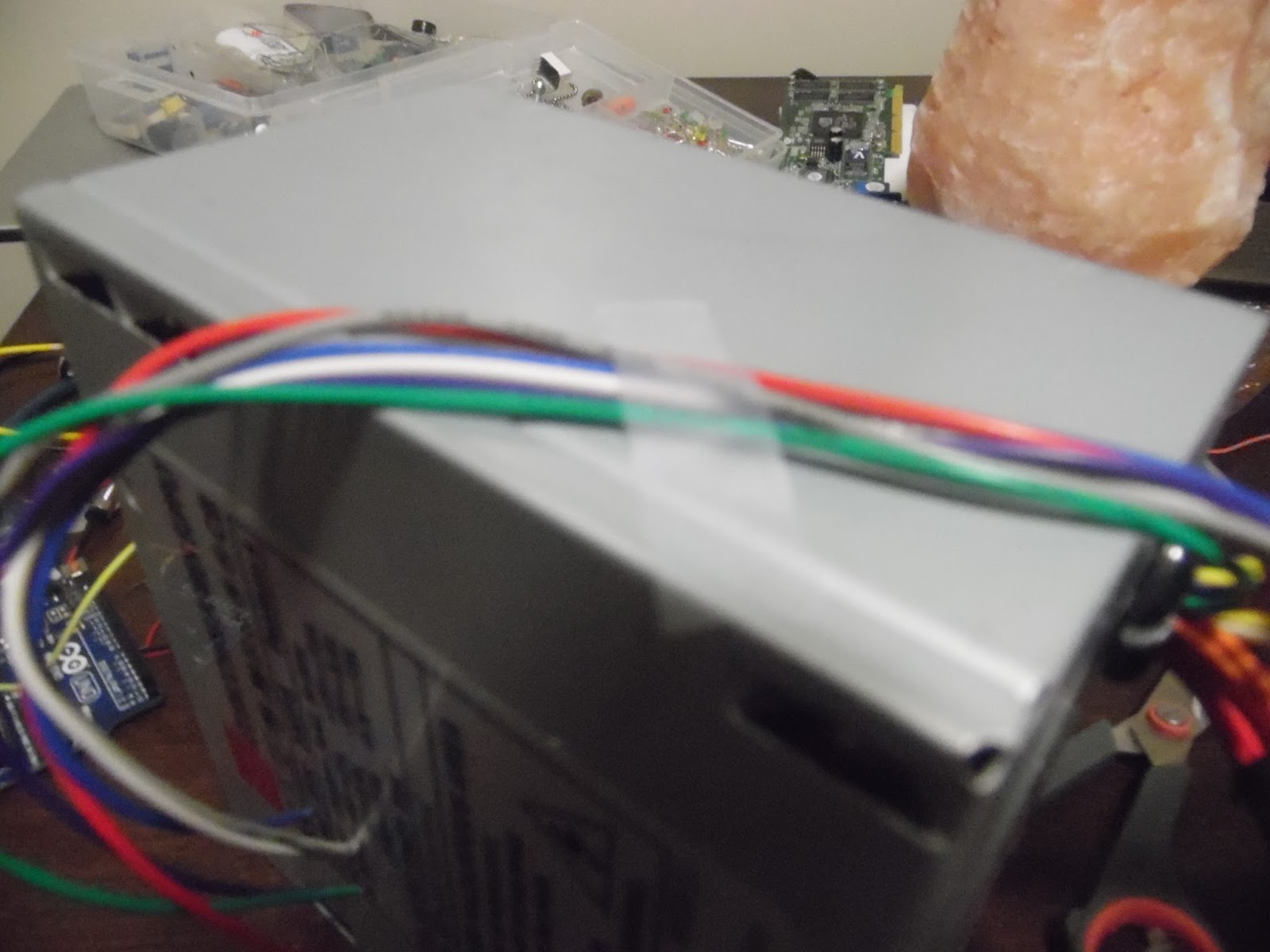
For this project I also recommend and I mean highly recommend using heat shrink to keep it clean and your wires pretty and protected. As well as a solder iron and basic power tools for cutting out your enclosure. Honestly I didnt have the proper cutting tools and it shows but I plan on covering my mistakes with coolness such as lcd display and possibly usb ports. **DANGER**As always be careful because the ATX unit carries a risk of electrocution and even stores a charge for quite some time even when unplugged so be careful.
STEP 1:
I chose to cut up the enclosure and install the hardware and make sure sure everything would fit properly. So trace or make a template that fits your space as well as your needs. I have seen many available to download on the internet so if you need help google it. I used a drill to cut out most of my holes, I also did resort to using a steak knife to cut and my gf's nail tool to sand edges lol.
So as you can see my holes are not picture perfect but let me defend that by saying I plan to put covers over the rough spots so you wont see em when I am done done. Anyways so for ventilation I made multiple holes in front and back of unit with drill. Again your feel to make your own mess.
Step 2: ADD HARDWARE After the holes are to your liking its now time to dress up this power supply. I chose three binding posts because thats all the power I could handle. You may need more. This step is super simple plus feels really satisfying seeing progress.
I installed all the binding posts then didn't like the placement so that's why I had a mess. (which will be fine) Also this is the perfect time for you to install the leds that will be used for showing when the power supply is on and also on standby mode.
After you have everything connected and looking nice we now move on to the best part. Time to play with some wires.
STEP 3:
This step is quite simple as long as you can handle a mess of wires. My advice is to keep it clean and simple. What we will be doing here is cutting all the wires to equal length and sorting by colour. Easy peasy. **DANGER** As I said before be aware of the dangers dont have the unit plugged in and as well discharge it.
Start by grouping the colours togther I used electrical tape and I am glad I did. Made for easy management later on. So you should have yellow, red, orange, black, green, blue,white,grey. You could have more or less depending on the model of psu you are using. If you are unsure google the model number and check out the data sheet.
This is the atx power supply I used. Check out the specs.
STEP 4:
Now its time to connect the wires to the correct places. So solder the groups of wire together and prepare to add your connectors. Depending on the size of your connectors will depend on the number of wires you can fit. I learned the hard way. After the group of wires are soldered place heat shrink over the wires and attach the connector. Fit the heat shrink to cover the wire as well as connector end and apply heat. Done and done. Next do the same with the grouping of orange wire. As well as red
Okay so before we proceed Ill give you a heads up. Keep in mind of things you would like to add that could affect your wire placement as well as wire count. I chose to add a 12v additional fan. This helps keep enclosure cool as well as a poor mans resistor. I used 1 yellow wire and one ground. So before you bunch all colours togther ask yourself how many do you need/ want. Again I learned the hardway.
Ok so the leds I installed serve two purposes. One they look cool and secondary they act as a standby indicator and a power good check. So it shows when the unit is just turned on as well as when it is in standby mode. In standby mode I believe the white wire provides a steady 5v
LED STANDBY/POWERGOOD/PUSHBUUTON
So with the first led connect the purple wire to the positive end and the negative end connected to negative with a 300ohm resistor in between. this will be the standby mode light. When it is light it is in standby mode.
Second led is to let you know that power supply is operating properly and is good. Same thing as before. Negative to negative wire with of course 300ohm resistor. The positive from led goes the the grey wire. I suggest yet again heat shrink and electrical tape. keep it clean. The button I used was easy to install. *Important*In order for the device to run properly the green wire needs to be connected to a ground wire. This is due to the fact the the device is designed to only run if it senses a load. To trick the unit you must connect the green to ground. Because my button is illuminated it required me to connect a 5v wire and ground to it as well as the green and ground. Your button is different so make sure you check your data sheet.
STEP 5: Now is the fun part. Time to connect the power to the bindings. This is where the connectors come in handy. Makes it very simple to just unscrew bindings and attach the wire group. As you can see from the picture you can find the colour groups here. Mine are as follows:
Orange: +3.3v
Black: ground
Red: +5v
Grey: Power ok
Purple: +5v SB
White: -5v
Green: PsON
Blue: -12v
Now its just a matter of attaching to the proper binding posts and you should be read to fire it up.
Enjoy and check back here for upcoming add ons and updates


 Hey there, so after scouring google and forums alike I finally found a circuit I could easily construct with the parts on hand. First off I was skeptical at first that I would see results, but I did! So as of now I am still playing around with the configurations and such. So you may ask what the hell is this that I am looking at.