Logo Design by FlamingText.com

Tuesday, 19 July 2016

**How 2 Connect Multiple Arduinos**


Eventually after many projects and impulse Ebay buys I have collected quite a few of the Arduino Uno micro controllers. I would like to think more = better. To be honest today was the first time I actually connected more then one to a power supply. Now that I know how easy it is to wire up and the extra applications you gain I will make better use of it. During my projects as of today I have never incorporated more then one, maybe one day. So if you would like a lesson on how to connect these bad boys, then keep scrolling. As always show some love and subscribe.


WHY WOULD YOU WANT TO RUN MULTIPLE ARDUINO'S AT ONCE?
Doing this allows you to communicate between two Arduino's and run different programs that can or will cooperate with each other. Other ideas could include wireless communicate between the two or three or ten devices. Pretty much the sky is the limit.  


Step 1:  Gather the materials


An Arduino or 2 or 3
Jumper Wires


Breadboard
PSU

STEP 2:  Assembly


Prepare your workstation by placing the breadboard and Arduinos closeby. Depending on the size of your jumper wires will determine how close. 

First things First

Jumper from ground to ground
You will need to power this devices. In order to provide power I have used my psu that I build. I covered this project in a previous blog if you would like to build your own.

Jumper from positive rail to VIN on Arduino
So I connected 5V to the breadboard by running a positive wire to the positive rail (red) and the ground to the ground rail (blue) on the breadboard.
The amazing thing I really love about using the breadbread is how with one easy connection you now have a whole rail you can draw power from. Makes things alot less messy.


STEP 3:  ADD MORE


Now you are able to repeat the process and add away. I connected three Arduino Uno's with no issue at all. Very simple to repeat. As well you could try this method as well if you wish to exclude the breadboard. 


Saturday, 16 July 2016

Creation Crate #1 DIY Arduino based RGB MOOD LAMP


So yesterday I received my very first Creation Crate package.  This months subscription included all the wonderful goodies required to build your very first RGB arduino based mood lamp. Before we dive into this build let me first say that if you are looking to start working with arduino then Creation Crate is the perfect start. They ship everything you need from start to finish and offer excellent guidance along the way. 


 This kit includes:

** Instructions
** An Arduino
** All Jumper cables
** Breadboard
** 3 Leds
** 1 Resistor
** A Light Dependent Resistor (LDR)
** The paper lamp cover
** Stickers
** Arduino Code ( Which I typed out and made it super simple for you to copy and paste in  the sketchbook.)

Breadboard
Resistors/LEDS/ jumpers


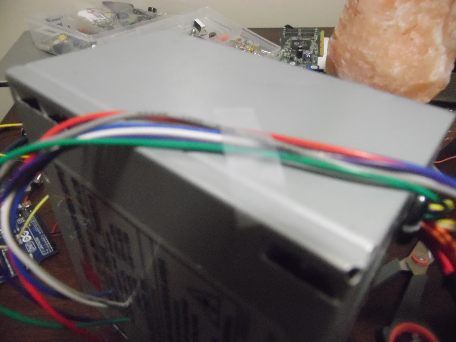
My DIY Power supply now up and running. Check BLOG for Step by Step build.
STEP 1: Placing the LEDS

Gather materials and place LED's onto the breadboard. The longer leg (of the led's facing towards you.

(Diode and LED Polarity. Diodes only allow current to flow in one direction, and they're always polarized. A diode has two terminals. The positive side is called the anode, and the negative one is called the cathode.


STEP 2: Placing the Resistors

Now take your resistor and LDR and connect those to the breadboard as shown. ** Make sure
that the two get connected on the same rail as shown in the picture.
 Step 3: Connecting the LEDS/ Resistors

Now we will begin by taking the 3 mini jumpers and connecting the led's. We do this by attaching the cathodes of the leds to the negative rail (blue) on the breadboard. Once they are all connected and you sit back and admire your progress then we move on.
As with connecting the cathodes (-) we must also connect the anodes(+). We do this by attaching the wires to the respected leds making sure we don't connect to the same rails. As you can see from the photos the breadboard is now coming alive.
The resistors also need to be connected to the breadboard as well. Run a jumper wire like I have from one end of the resistor and connect it to the 5v rail (red). Next you need to complete the circuit by now attaching the free end of the LDR to the ground rail on the breadboard (blue)
after this has all been arranged you now have finished the trickiest part. Looks amazing doesn't it. Next step is setting up the arduino on your laptop or pc.
Step 4: Connecting to the Arduino


The connection to the arduino from your breadboard are quite simple to understand. The arduino is labelled with numbers which make pin connections fairly simple. Basically it will say connect this to this pin and so on. So here we go                                                                                                   RED  LED : Pin (11)                                             GREEN LED: Pin (10)                                            BLUE LED: Pin (9)                         LDR: Pin (Analog 0)


Step 5: Hooking up the Arduino and Code


After you have completed the circuit now comes the exciting part of bringing your Creation Crate alive. Plug the usb into your computer and install the 
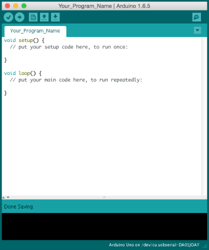
arduino program. This is free.  After the install, open up the Arduino program. You will be greeted with this window which is called a sketchbook. The sketchbook allows you to write code and then upload it directly to your arduino board. The program includes alot of free codes already written for you to enjoy and is as simple as selecting your needs. This is the bread and butter of the Arduino world.
So once in the sketch window all you now need to do is copy the following code and place it in a blank sketch. Click upload and bammm you should be up and running.


*******CODE: 


int pulseSpeed = 5;    // how fast lamp runs

int ldrPin = 0;        // LDR in Analog input 0
int redLed = 11;       // red led in digital pin 11
int greenLed = 10;     // green led in digital pin 10
int blueLed = 9;      // blue LED in digital pin9

int ambientLight;    // stores the value of the light in the room

int power = 150;     // brightness 2-255

float RGB[3];        // this is an array

float CommonMathVariable = 180/PI;   

void setup () {
  
  pinMode(redLed,OUTPUT);
  pinMode(greenLed,OUTPUT);
  pinMode(blueLed,OUTPUT);
  
  digitalWrite (redLed,LOW);
  digitalWrite (greenLed,LOW);
  digitalWrite (blueLed,LOW);
  
  // this sets all the outputs to off
  
}

void loop (){
  for (float x = 0; x < PI; x = x + 0.00001){
    
    RGB[0] = power * abs(sin(x * (CommonMathVariable)));
    // Red
    
    RGB[1] = power * abs(sin((x + PI/3) * (CommonMathVariable)));
    // green
    
    RGB[2] = power * abs(sin((x + (2 * PI)/3)*(CommonMathVariable)));
    
    ambientLight = analogRead(ldrPin);
    // reads light and stores
    
    if (ambientLight > 600) {
      // makes the light only turn on if dark
      
      analogWrite (redLed,RGB[0]);
      analogWrite (greenLed,RGB[1]);
      analogWrite (blueLed,RGB[2]);
      
    }
    else {
      digitalWrite (redLed,LOW);
      digitalWrite (greenLed,LOW);
      digitalWrite (blueLed,LOW);
    }
    
    for (int i = 0; i < 3; i++) {
      
      if (RGB[i] < 1) {
        delay (20 * pulseSpeed);
      }
      else if (RGB[i] < 5) {
        delay (10 * pulseSpeed);
      }
      else if (RGB[i] < 10) {
        delay (2 * pulseSpeed);
      }
      
      else if (RGB[1] < 100){
        delay (1 * pulseSpeed);
      }
      
      else {}
    }
    delay(1);
  }
}


Finished:


Check back soon for next months build.

Creation Crate and what is Creation Crate?


So for fathers day I was lucky to receive a monthly subscription to a very very cool program called CREATION CRATE. Basically once a month they send a package which contains all the components required to build an arduino based project. These projects are super cool and very simple for the beginner. I was super excited and waited what seemed like forever to recieve my package. No fault on their end. (Canada post strike thing) Regardless yesterday I got my package and I went to work building.

To be honest I had and have most of the parts they send but I really enjoy one having more and two how clean and easy the instructions are. The package comes with a booklet outlining step by step directions which makes it very and I mean very user friendly. As well as instructions they even include the coding required to program your arduino.

A typical monthly box will include sooooooo much to keep you busy, each month you get another arduino and breadboard ( my favorite) as well as the other parts depending on the project of the month. WHATS INSIDE?

To order your own subscription feel free to drop by Creation Crate and check out the plans they have and decided on what suites your needs.


This month I was sent the Creation Crate DIY Mood Lamp. Check out my monthly Creation Crate builds which you can find on my blog. As well if you have any questions I will gladly try my best to get back at ya.


Questions? check out the FAQ


Monday, 11 July 2016

DIY Complete Arduino Project Bench with ATX Power Supply


After weeks of research and planning as well as waiting for all the parts to be shipped I finally built and finished this amazing project. The aim was to build a power supply without spending a dime... ya that's right this build was free. After quite some time of tinkering with arduino and breadboarding electronics I was getting really annoyed at the lack of options for power and the hassle of unhooking and limited build because of power issues. I then stumbled apon many different versions of the bench top power supply. I noticed however that none of these builds seemed specific for what I was looking for so away I went. I would like to thank all of the suppliers who worked with me and provided the materials needed for this project. Links as well as resources will be included for your own needs.

This power supply is quite handy for many functions. Mine includes three seperate binding posts for different ranges of power such as: +3.3v, +5v, +12v as well as options to expand. Which will be updated as I progress and addon. The cool part of this I believe is in the enclosure itself as it acts as a perfect surface to breadboard as well as operate an ARDUINO or ARDUINO'S lol like I plan.
This project is very easy to do and once built it will allow a cleaner look as well as endless possibilities.

Materials:

- ATX power supply: To provide the power

 You can salvage one from an old pc like I did plus you can score extra goodies from dismantling a pc

- Enclosure or box or whatever you plan to use: To enclose your project 

I used a enclosure from OKW ENCLOSURES INC.  These guys can help out with custom enclosures of all sorts. You can check them out @ http://www.okusa.com/

- Binding Posts: Used for connecting

I lucked out and found a great supplier CHK ELECTRONICS who was eager to help and provided sweet binding posts you can check out the site @ http://www.chk-electronics.com/home.php

- Leds: Used to display standby mode as well as power good mode

I scored yet again and found a great site and company BIVAR LED who was willing to help a brother out you can check it out @ http://www.bivar.com/

- Resistors: I used two 300ohm resistors each one attached to the negative leg of each led. It was all I had in my tackle box

- 12v pc fan: Acts in place of minimum load required to operate atx

I didnt have a 10w sandbar resistor so I figured if the atx needs something to draw minimum current why not just use a fan. This way it doubles as a cooling unit as well as provides the resistance... I could be wrong but it made sense to me.
Salvaged from the pc I killed

- Illuminated Push button: Serves as an on/off

I chose to use an illuminated button for two reasons. One, it looks mint and as well provides a good function to be able to turn source on and off. I was lucky to get a supplier NKK SWITCHES who helps out quite often with my projects. They have a ton of product at great prices. You can check em out @ http://www.nkkswitches.com/products/illuminated-pushbutton/


For this project I also recommend and I mean highly recommend using heat shrink to keep it clean and your wires pretty and protected. As well as a solder iron and basic power tools for cutting out your enclosure. Honestly I didnt have the proper cutting tools and it shows but I plan on covering my mistakes with coolness such as lcd display and possibly usb ports. **DANGER**As always be careful because the ATX unit carries a risk of electrocution and even stores a charge for quite some time even when unplugged so be careful.


 STEP 1:

                                                                                I  chose to cut up the enclosure and install the hardware and make sure sure everything would fit properly. So trace or make a template that fits your space as well as your needs. I have seen many available to download on the internet so if you need help google it. I used a drill to cut out most of my holes, I also did resort to using a steak knife to cut and my gf's nail tool to sand edges lol.

So as you can see my holes are not picture perfect but let me defend that by saying I plan to put covers over the rough spots so you wont see em when I am done done. Anyways so for ventilation I made multiple holes in front and back of unit with drill. Again your feel to make your own mess.


Step 2:

ADD HARDWARE

After the holes are to your liking its now time to dress up this power supply. I chose three binding posts because thats all the power I could handle. You may need more. This step is super simple plus feels really satisfying seeing progress.


 I installed all the binding posts then didn't like the placement so that's why I had a mess. (which will be fine) Also this is the perfect time for you to install the leds that will be used for showing when the power supply is on and also on standby mode.


After you have everything connected and looking nice we now move on to the best part. Time to play with some wires.

STEP 3:


This step is quite simple as long as you can handle a mess of wires. My advice is to keep it clean and simple. What we will be doing here is cutting all the wires to equal length and sorting by colour. Easy peasy. **DANGER** As I said before be aware of the dangers dont have the unit plugged in and as well discharge it.

 Start by grouping the colours togther I used electrical tape and I am glad I did. Made for easy management later on. So you should have yellow, red, orange, black, green, blue,white,grey. You could have more or less depending on the model of psu you are using. If you are unsure google the model number and check out the data sheet.


 This is the atx power supply I used. Check out the specs.

STEP 4:


Now its time to connect the wires to the correct places. So solder the groups of wire together and prepare to add your connectors. Depending on the size of your connectors will depend on the number of wires you can fit. I learned the hard way. After the group of wires are soldered place heat shrink over the wires and attach the connector. Fit the heat shrink to cover the wire as well as connector end and apply heat. Done and done. Next do the same with the grouping of orange wire. As well as red


Okay so before we proceed Ill give you a heads up. Keep in mind of things you would like to add that could affect your wire placement as well as wire count. I chose to add a 12v additional fan. This helps keep enclosure cool as well as a poor mans resistor. I used 1 yellow wire and one ground. So before you bunch all colours togther ask yourself how many do you need/ want. Again I learned the hardway.

 Ok so the leds I installed serve two purposes. One they look cool and secondary they act as a standby indicator and a power good check. So it shows when the unit is just turned on as well as when it is in standby mode. In standby mode I believe the white wire provides a steady 5v

LED STANDBY/POWERGOOD/PUSHBUUTON


So with the first led connect the purple wire to the positive end and the negative end connected to negative with a 300ohm resistor in between. this will be the standby mode light. When it is light it is in standby mode.

Second led is to let you know that power supply is operating properly and is good. Same thing as before. Negative to negative wire with of course 300ohm resistor. The positive from led goes the the grey wire. I suggest yet again heat shrink and electrical tape. keep it clean.  The button I used was easy to install. *Important* In order for the device to run properly the green wire needs to be connected to a ground wire. This is due to the fact the the device is designed to only run if it senses a load. To trick the unit you must connect the green to ground.  Because my button is illuminated it required me to connect a 5v wire and ground to it as well as the green and ground. Your button is different so make sure you check your data sheet.


STEP 5:


Now is the fun part. Time to connect the power to the bindings. This is where the connectors come in handy. Makes it very simple to just unscrew bindings and attach the wire group. As you can see from the picture you can find the colour groups here. Mine are as follows:

Orange: +3.3v
Black: ground
Red: +5v
Grey: Power ok
Purple: +5v SB
White: -5v
Green: PsON
Blue: -12v

         Now its just a matter of attaching to the proper binding posts and you should be read to fire it up.

Enjoy and check back here for upcoming add ons and updates