Logo Design by FlamingText.com

Monday, 25 July 2016

Arduino Lesson#6: Continued Programming

Lesson#6: Programming


For this lesson we will continue as before and learn more about the println and print functions. Copy and paste the following code into your sketchbook and upload it to the Arduino board. We are going to make a calculator.

a2 + b 2 = h 2
h = (a2 + b2)
 If you remember from grade school, if you have a right-triangle, the hypoteneuse h can be calculated from the lengths of the two legs, c1 and c2 (which we'll call a & b)
/*
 * Math is fun!
 */

#include "math.h"               // include the Math Library

int a = 3;
int b = 4;
int h;

void setup()                    // run once, when the sketch starts
{
  Serial.begin(9600);           // set up Serial library at 9600 bps

  Serial.println("Lets calculate a hypoteneuse");

  Serial.print("a = ");
  Serial.println(a);

  Serial.print("b = ");
  Serial.println(b);
  
  h = sqrt( a*a + b*b );
  
  Serial.print("h = ");
  Serial.println(h);
}

void loop()                // we need this to be here even though its empty
{
}
The first thing that's new here is this line at the very beginning of the sketch:
#include "math.h"               // include the Math Library header
Which basically says "We'd like to use the math procedures, which are in a library that requires us to include the file math.h where the sqrt procedure lives". Just ignore it for now, it's not important.
The second thing that's different here is that when we create the variable h we don't assign it a value.
int h;
It turns out that this is totally OK, it just means that we don't know what is going to store yet, because we're going to calculate it later. Since it's not assigned to a value upon creation, the Arduino just creates the box, the stuff inside is whatever was in left over in memory.
Default values
If you don't assign a value to a variable, it could be any value. Make sure you don't try to use the variable before you assign it a value!
Later on in the sketch, we assign it the value.
   h = sqrt( a*a + b*b );
In this line, we square a and b and then add them together, then we call the sqrt() procedure (which does exactly what you may think), to take the square root. Then we assign that to the variable h.
Variable
=
Value
;
Whatever was in before is lost, replaced by the new value.
You can nest procedures and functions all you want, calling a procedure on the return value of another procedure.


Arduino Lesson#5: Lets Program


Lesson#5: Intro Programming

Ok after the success of the last lesson we can now move onto something a bit more challenging. In this lesson we will learn more about the serial display uses. With this example we can see how we can create a simple math machine. Copy and paste the following code into your Arduino and upload away.

/*
 * Math is fun!
 */

int a = 5;
int b = 10;
int c = 20;

void setup()                    // run once, when the sketch starts
{
  Serial.begin(9600);           // set up Serial library at 9600 bps

  Serial.println("Here is some math: ");

  Serial.print("a = ");
  Serial.println(a);
  Serial.print("b = ");
  Serial.println(b);
  Serial.print("c = ");
  Serial.println(c);

  Serial.print("a + b = ");       // add
  Serial.println(a + b);

  Serial.print("a * c = ");       // multiply
  Serial.println(a * c);
  
  Serial.print("c / b = ");       // divide
  Serial.println(c / b);
  
  Serial.print("b - c = ");       // subtract
  Serial.println(b - c);
}

void loop()                     // we need this to be here even though its empty
{
}


Check out the above code. Did you notice anything new? We have covered the "println" procedure but not the "print".  The print procedure is just like println except it does not print out a "carriage return" at the end, starting a new line.

Ok so now lets dissect this code a little bit now.

  Serial.println(a);
 If you use a quoted line of text as input to println procedure, it will display that text. In this case you can see that if you use a variable to println it will look up what that variable contains and print that out!

  Serial.println(a + b);
 Arduino looks at what the input to println is, and finds its actually a calculation. It looks up what a is (5) and what b is (10) and then adds them together (+) and then uses that as the value to send to println


Arduino Lesson#4: Hello World

Lesson#4: Hello World


Finally we are making waves, hopefully you are following along and grasping at the straws I am throwing your way. This lesson will teach you how to get your fancy Arduino talking, well not yet but it will display words. We will get to sounds soon enough.


STEP#1: Getting Started

Open up your Arduino sketchbook and create a new sketch and name it "Hello World".
Next copy and paste the following code into your sketchbook.

/*
 * Hello World!
 *
 * This is the Hello World! for Arduino. 
 * It shows how to send data to the computer
 */


void setup()                    // run once, when the sketch starts
{
  Serial.begin(9600);           // set up Serial library at 9600 bps
  
  Serial.println("Hello world!");  // prints hello with ending line break 
}

void loop()                       // run over and over again
{
                                  // do nothing!
}

Ok lets get to work, notice how the loop is empty. Regardless the arduino requires the "setup" and "loop" to be included in the sketch even if they arent doing anything.

Take a look at the first line of code in the "setup" procedure.
   Serial.begin(9600);           // set up Serial library at 9600 bps
First thing we see is the word "Serial" as you read it looks as if this may be a procedure call as well. This is defined as a libary procedure call. The library is named "Serial" and in that library is a procedure called begin.
library name
.
procedure name
(input values)
;
Serial
.
begin
(9600)
;

begin: This is a procedure that gets the serial things ready.
bps: This stands for bits-per-second aka baud rate
OK so Serial.begin sets up the Arduino with the transfer rate we want, in this case 9600 bits per second.
Now on to the next line.
Serial.println("Hello world!");  // prints hello with ending line break 
Again the Serial library, but this time it's using a procedure called "println" 
printIn: This is short for print line
Upload the sketch to your Arduino and continue to the next step.

STEP#2:

Once you have uploaded the sketch to your Arduino you should see...... nothing new lol.
Do not worry though the reason nothing seems to be happening is because we need a monitor to view the serial data happening. Lucky for us, Arduino has one built right into the Arduino sketch program. Different versions of Arduino have different locations to find the "Serial Monitor".

As you can see mine is easy to locate. Once you find yours click it.


Depending on the type of Arduino you are using you may get different results such as resetting the uno then the sketch will run  either way it will run. It may just be a matter of waiting seconds longer. You should now see your hard work paying off. If you experience what looks like mashing of the keyboard try changing the "baud rate". This is located in the lower right corner. ** Try clicking on the reset button and see what happens.


/*
 * Hello World!
 *
 * This is the Hello World! for Arduino. 
 * It shows how to send data to the computer
 */


void setup()                    // run once, when the sketch starts
{
  Serial.begin(9600);           // set up Serial library at 9600 bps
}

void loop()                       // run over and over again
{
  Serial.println("Hello world!");  // prints hello with ending line break
  delay(1000);
}


Still wanna play around? Why not play around with this code. Play around with the delay(500)? or even be crafty and change the Serial.println("I'M LEARNING")

Proceed to Lesson#5


Arduino Lesson#3: Serial Libraries

    Lesson#3: Serial Libraries


In this lesson we will begin talking about the Arduino libraries. The libraries can be understood as a collection of procedures to get a task from point a to point b. For instance if you would like to play with dc motors you could use the motor control library. This would allow you to use a working sketch to get your motors moving without the hassle of learning everything you would need to know about motors. 
In this lesson we will be learning about the Serial Libary.

Serial Library: This library will allow the Arduino to send information to the computer. The word "serial" means "one after the other". So serial data transfer is sending data one bit at a time one after another. Information can be transfered back and fourth between the computer and Arduino by setting a pin to either "HIGH" or "LOW".  Remember one side sets the pin and the other one reads it.

Included in the Arduino sketchbook are lots of libraries ready for you to employ, it is as simple as selecting the appropriate sketch and uploading to your Arduino. Now a lot of Arduino projects require you to connect outside devices and wires and such, this now opens up room for you to explore breadboarding. Using a breadboard allows you to connect your electronics without solder. Perfect for the newb.


Bits & Bytes:  Used to measure amount of data

single bit is either a zero or a one
You can group bits together into 8 bits which is 1 byte
1024 bytes (8192 bits) is one Kilobyte (sometimes written KB).
1024 KB (1048576 bytes) is one Megabyte (MB)
1024 MB is 1 Gigabyte (GB)


Where to find libraries?


To locate the libraries you need to open the Ardunio icon on your desktop and select FILE---> EXAMPLES.
Find the examples you would like to use and upload it to the Arduino. Super simple. Take note on the comments of the sketch and be aware of the pins being used.


Next lesson: HELLO WORLD 

Arduino Lesson#2: Understanding Lesson #1

Lesson # 2: Understanding Code


Congratulations for completing your first lesson and running your first sketch. Like I mentioned in lesson 1, having pre written code can be quite useful in order to learn from. For me I used plenty of code to save time and also to modify from. In this lesson we will go over some basic topics to get you on your way to understanding what the hell is happening. Lets take a closer look at the sketch from lesson 1.


Arduino "Blink" Sketch:


/*
 * Blink
 *
 * The basic Arduino example.  Turns on an LED on for one second,
 * then off for one second, and so on...  We use pin 13 because,
 * depending on your Arduino board, it has either a built-in LED
 * or a built-in resistor so that you need only an LED.
 *
 * http://www.arduino.cc/en/Tutorial/Blink
 */


int ledPin = 13;                // LED connected to digital pin 13

void setup()                    // run once, when the sketch starts
{
  pinMode(ledPin, OUTPUT);      // sets the digital pin as output
}


void loop()                     // run over and over again
{
  digitalWrite(ledPin, HIGH);   // sets the LED on
  delay(1000);                  // waits for a second
  digitalWrite(ledPin, LOW);    // sets the LED off
  delay(1000);                  // waits for a second
}

The sketches we work with are written in "C", this is a powerful and very popular programming language, I will warn you it does take abit to get used to but with practice it will be a breeze.
We will dived up the sketch and discuss the different functions as well as what does what.


1#  Comments:   Comments are very important with programming. This allows you to write your code and then place comments beside to indicate what that code will do. To do this, notice the use of
" /* " and " */ " in the first line of code. This is basically like a bracket. Anything inside will be ignored by the arduino. It is for the user to input details about the code. Make a point of starting your code with a comment indicating the code and what its function plans to be. ** You can also comment things by using " // " and then typing your comment. You will notice what I mean as you continue the lesson.

/*
 * Blink
 *
 * The basic Arduino example.  Turns on an LED on for one second,
 * then off for one second, and so on...  We use pin 13 because,
 * depending on your Arduino board, it has either a built-in LED
 * or a built-in resistor so that you need only an LED.
 *
 * http://www.arduino.cc/en/Tutorial/Blink
 */


2#  Variables:   This is the first line we see of the code itself, to the right of the code you will notice it has a comment detailing the code.  FYI all computer sentences end with a " ; ".
So basically we are looking at a computer sentence. This sentence is telling the computer that we want to create a box named "ledPin", and to put the number 13 in that box.

int ledPin = 13;                // LED connected to digital pin 13


box-type
box-name
=
stuff-to-put-in-box
int
ledPin
=
13

int: short for integer or whole number 
ledPin: name of the box
= :  which basically says that the variable (box) named ledPin should start out equaling whatever is after the = 13: a whole number (integer) which is assigned to ledPin

3# Procedures:  Used to group statements together so they can be referred to with one name. Think of it like step by step.


void setup()                    // run once, when the sketch starts
{
  pinMode(ledPin, OUTPUT);      // sets the digital pin as output
}
Here we see in the middle there is a statement, we know its a statement because it ends with a ;
This bunch of code is an example of a procedure, a procedure is a collection of statements,

returned value
procedure name
(input values)
{ statements }
void
setup
()
pinMode(ledPin, OUTPUT); }


As we look at the procedure, we see that it is named setup and it has no input values and it returns void
What is "VOID"?  Void basically means there is nothing to do. There is nothing to show or do.


void setup()                    // run once, when the sketch starts
There is one statment in this procedure,
pinMode(ledPin, OUTPUT);      // sets the digital pin as output
4#  Procedure calls:   

void loop() // run over and over again
{
digitalWrite(ledPin, HIGH); // sets the LED on
delay(1000); // waits for a second
digitalWrite(ledPin, LOW); // sets the LED off
delay(1000); // waits for a second
}
As you may notice we have a new procedure, this one called loop which also has no inputs or output. This procedure has multiple statements, one after the other.  This code tells arduino to stop for a little bit.

To do this, the statement performs a procedure call.
procedure name
(input values)
;
delay
(1000)
;
This means that somewhere out there, there's a procedure something like this: 
void delay(number of milliseconds)
{
"Dear Arduino. Stop what you're doing for (number of milliseconds)
}
As you hopefully notice the first statement is "digitalWrite" this is saying here turn on the light, wait a second turn it off wait a second turn it on. And over and over and over lol


Final notes: Keep in mind the Arduino will always do whats included in the setup first and then will do the loop over and over and over and over.


Arduino #1 Lesson: "Hello World" Blink an LeD

LESSON 1: BLINK
This first lesson will teach you how to use the hardware and software together to make the led light up. 

Now that we are familiar with the Arduino and have installed the program on our computer we can now move on to the first lesson.
Once you get comfortable operating the sketchbook we move on to the more exciting stuff.


STEP 1: Gather your equipment.


For this first lesson you will only need a few things to get the project up and running. You will need:

* Arduino
* Laptop or PC
* USB connector cable
* LED is optional most Arduinos will have a built in LED to test with. You can change sketch to use a different pin and use an led of your choice. 


STEP 2:  Open the Software


***OPEN ARDUINO PROGRAM***


First things first click on the Arduino icon that you have installed onto your desktop. Once opened you will be brought to the Arduino sketchbook. This is where the magic happens. The sketchbook is used to input the code that will be uploaded to the Arduino, it is fairly simple to use once who get familiar navigating around. When you open it up you will be met with a window such as the picture shown.

***Next*** 


Go to the File menu -> Sketchbook -> Examples -> Basics -> Blink


Once you select the "BLINK" sketch a window will pop up which will look like this picture. This is the code we will be using for our very first lesson. Thankfully someone came along and did the hard stuff for us. The beauty of using these prewritten codes is that we can learn alot by examples. For example you can fiddle around and change output pins for the led.  Another advantage of learning by examples is that if you notice on the sketches they have explanations of the codes alongside.
( // wait for a second )


So after you have this sketch in front of you the next step is to load it onto the Arduino.


STEP 3:  Connection Time


*** Connecting Arduino to Sketchbook ***


Start off by connecting one end to the Arduino and the free end connected to either your laptop
or you pc.

We are on our way to completing our first program. Hang in there. Once connected to your source ( laptop or pc) you will need to do acouple more things before we move on.


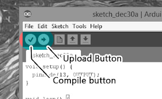
In order to transfer the "Blink" sketch onto the Arduino we firstly need to make sure that the code was been written properly and will work. One of the best things is how the programs has a built in checker that will verify that it makes sense and will run. If the coding isnt correct the sketch will be unable to load. If this happens you will recieve an error message detailing where you went wrong. We will cover common errors in a different post.


As you can see from the picture you have some options when it comes to finishing up on this project. First click on the "Compile" button. This runs a scan of your code and will make sure it is correct.
Next it will ask you to save. Save sure.

Lastly I would like you to click "Upload"

BAMMMM!


STEP 4: COMPLETE
Led "on"

EXTRAS:


If you are not done playing around you could also try playing around with the code. Maybe change the outputs? Add more leds? The photo on the left shows an led connected directly to the arduino.

Connect the led to Arduino by placing  "cathode" of the led ( - ) to the ground pin on Arduino. Place "anode"(+) to pin 13 on the Arduino. 


Sunday, 24 July 2016

WTF is ARDUINO?


Up intil a few years ago I had never pictured myself being as involved and interested in the world of electronics as I currently am, It all started from a late night Ebay stroll, 3 weeks later I was fixated. The Arduino world allows a total newb to jump on board and progress at a comfortable pace without overwhelming and confusing the user. The word "Arduino" can mean a few things, it can be meat as the board itself which is the hardware, it is also a software program which is how you program the hardware unit itself.


" Arduino is a hardware and software company, project, and user community that designs and manufactures computer open-source hardware, open-source software, and microcontroller-based kits for building digital devices and interactive objects that can sense and control physical devices." SOURCE


    This is called an " Arduino Uno" The Arduino Uno is a microcontroller board based on the ATmega328 (datasheet). It has 14 digital input/output pins (of which 6 can be used as PWM outputs), 6 analog inputs, a 16 MHz crystal oscillator, a USB connection, a power jack, an ICSP header, and a reset button.


Install the Arduino Software by simply pluging in the usb to your laptop or pc and await the installation popup.Once that is all done, Click the Arduino icon that you so wisely installed on your desktop for easy access.


   *** That's it ! Next its time to compose your first sketch ***

BEST PLACE 4 GTA GLITCHES


*** GTA 5 ONLINE *** 


--Looking 4 Glitches?
--Wanna Mod?
--Hack?
--Be a BOSSSSS


If you are like me and are awesome then you will definitely appreciate this link http://www.se7ensins.com/forums/threads/next-gen-dupe-glitch.1533635/page-169


I have been playing GTA since the dawn of the "O.G GTA1" and from day one I have cheated and I have no intention of playing any differently. The site above leads to a gaming forum which I use religiously. They have made me millions and millions. As of today there is a glitch available to duplicate your cars and resell. I encourage ya'll to stop watching the lame youtube vids which promise you sharkcard after sharkcard and survey bullshit things and seriously check these guys out.


Not only do they provide all platforms for cheats/ glitches/ walkthroughs but the members are on top of there A game and will gladly help ya out. I cannot say enough good things about this site.  

My advice is bookmark the shit outta the site and check back on the reg.

Wednesday, 20 July 2016

LED LESSON #1


In this quick lesson we will go over a very simple hook up in order to make an LED of your choice shed some light. In order to do this we will need to gather a few key elements in order to get this project off the ground. Leds can be used for anything and everything, they are perfect to add accents and lighting to your home, car or anywhere else. Nowadays people have shifted focus on using led strip lighting which offers easy installation as well as being easy to control. By following this walkthrough you should be able to understand the setup as well as the concept, so get ready and keep reading. 


STEP 1: Gather your gear
For this project you will need:
- L.E.D  ( Light emitting diode )
- 220 ohm resistor
- Breadboard
- jumper wires


Light Emitting Diode (L.E.D)
                                   LED

When placing the led onto the breadboard you need to know the orientation of the led itself. Take a look at the led description and get familiar with the different functions. The led in this case has two legs. The longer leg is called an "Anode" this leg is defined as positive (+). This is generally connected to the positive power supply. The shorter leg called an "Cathode" is defined as being the negative pin, which is connected to the ground through a resistor which we will discuss next.


Resistor

Resistors can be used in many different ways, they are mainly responsible for protecting components from being damaged such as in leds. They are the dams of electricity, different resistors can allow different flows to pass through. Resistors can split voltage between parts of a circuit as well as  control delays. Most resistors nowadays are carbon. Resistors have values assigned which are rated by the colours on them. The colours used are : black, brown, red, orange, yellow, green, blue,purple, gray, and white. The colours represent a different number. Black = 0 Brown= 1 all the way to White = 9.   Remember these numbers you will need to learn which applies to which.


STEP 2: Connections


First things first connect your power supply. I chose as always my own created "PSU"  Connect 5v to positive rail on the breadboard (red +) and ground will be connected to the blue breadboard rail (ground). Next insert the led (colour of your choice) into the breadboard as shown in the picture. For more information on how to use a breadboard you can check out my walk through which you will find in my project listings. Place "Anode" in one opening and "Cathode" in its own hole.


Now that the led and the power supply are connected we now move onto connecting the resistor. To do this we need to place the resistor with one end connected to the same rail as the cathode of the led. The other end of the resistor is in its own hole as well. Now place your jumper wires.


Connect the resistor with your jumper wire. One end of the jumper wire will be connected to the cathode end with the other end connected to the ground rail of the breadboard. Now we need power.


To do this we connect another jumper. This wire is connected to the anode of the led. This wire now gets connected to the red rail which will provide the 5v power needed to run the led.


Beautiful eh, if everything went smoothly then you should be sitting back relaxing and enjoying your progress. Some common issues if you cannot make light would be:

-LED is installed backwards
-improper power supply
-dead led