Hey there, just a quick little snippet of a cool coil and its abilities. This is fairly simple to build and really cool to play around with. The coil is being powered by a 1.5 volt battery and can go upwards of 9 volts..... 12volts and things start smoking lol, make sure you use appropriate resistors
This was a super simple build, which me and my lil guy threw together on a past weekend, it runs off an arduino which is then powered by a 9 volt battery, Eight different coloured leds were used as well as eight glue sticks to add in the cool effects. As well I have added a 10k pot which allows adjustment for the speed of flash.
Code: The sketch is very simple you can either just google it, write it, or just copy and paste you lazy bastard u.
// 8 LED's are connected to the 8 Pins of Arduino
// with a series resistor with each LED
// Potentiometer is Connected to Analog Input pin A0
// refer circuit diagram for reference
// You can Change chaser speed by varying the pot
int led1 = 1;
int led2 = 2;
int led3 = 3;
int led4 = 4;
int led5 = 8;
int led6 = 9;
int led7 = 10;
int led8 = 11;
int count = 1;
void setup()
{
// put your setup code here, to run once:
pinMode(1,OUTPUT);
pinMode(2,OUTPUT);
pinMode(3,OUTPUT);
pinMode(4,OUTPUT);
pinMode(5,OUTPUT);
pinMode(6,OUTPUT);
pinMode(7,OUTPUT);
pinMode(8,OUTPUT);
}
void loop()
{
// i reads the analog pot value connected to A0 pin
// this value changes from 0 - 1023 giving us a delay of
// 0 to 1023 milliseconds
// count variable carries the number of LED pin
// we reset the count to 1 when it becomes more than 8
A joule thief is a self-oscillating voltage booster that is small, low-cost, and easy to build, typically used for driving small loads. This circuit is also known by other names such as joule ringer or blocking oscillator.
It can use nearly all of the energy in a single-cell electric battery, even far below the voltage where other circuits consider the battery fully discharged (or "dead"); hence the name, which suggests the notion that the circuit is stealing energy or "joules" from the source. The term is a pun on the expression "jewel thief": one who steals jewelry or gemstones.
The circuit is a variant of theblocking oscillatorthat forms an unregulated voltage boost converter. The output voltage is increased at the expense of higher current draw on the input, but the integrated (average) current of the output is lowered and brightness of a luminescence decreased.
I have been playing around with this circuit for quite some time and I am very interested in it's applications, it is very simple to build and quite pleasant to watch the results.
Follow these instructions in order to build your own version, later on I will show you some cool experiments I have been working on, using a joule thief plus crystal radio, as well as a joule thief combined with another cool circuit that for the life of me I forget the name, but I came across it while researching Tesla cosmic energy collector. Basically this circuit allows current to be collected from an antenna and it runs forward using diodes and is ran into a capacitor which stores the charge. I have been quite successful in lighting leds.
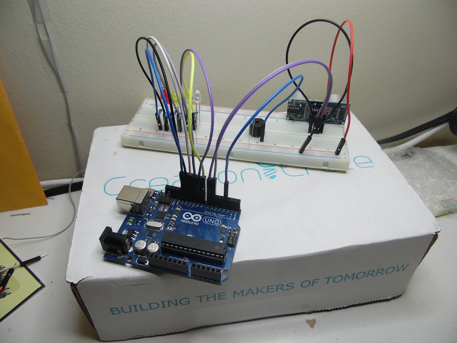
This months project is a really cool and simple build distance sensor using leds as well as a buzzer, with of course Arduino. For me I appreciated getting the ping sensor mainly because I only have one and its in use now so having two is handy.
As you can see included in this months delivery were as follows:
Begin by placing leds into breadboard negative facing left, as well insert buzzer and sensor. This setup is quite simple and their isnt really much work making these connections. if you find your leds are not lighting up try flipping them.
Step#2: Now its time to place the resistors. Place each resistor to one end of each led. They are connected to each negative end to the resistor. Next complete by placing resistor on the negative end of the buzzer.
Step#3: Connecting to Arduino
Gather you jumper wires and connect one end from each led the leds are connected to the Arduino digital in pins. Pin 8-12. Next the Buzzer is connected to pin 3. The sensor is connected to 5v, ground, and trig is connected to pin 6 and echo is connected to pin 6. I shouldnt have to mention ground to ground on arduino and 5v to 5v....
Step#4: Load Up Code
// License: GNU General Public License
// Creation Crate Month 3 - Distance Detector
#define red2 13
#define red1 12
#define yellow2 11
#define yellow1 10
#define white2 9
#define white1 8
#define buzzer 3
#define trigPin 7
#define echoPin 6
int sound = 250;
long duration, distance;
void setup() {
// put your setup code here, to run once:
Serial.begin(9600);
pinMode(trigPin, OUTPUT);
pinMode(echoPin, INPUT);
pinMode(white1, OUTPUT);
pinMode(white2, OUTPUT);
pinMode(yellow1, OUTPUT);
pinMode(yellow2, OUTPUT);
pinMode(red1, OUTPUT);
pinMode(red2, OUTPUT);
pinMode(buzzer, OUTPUT);
}
void loop() {
// put your main code here, to run repeatedly:
// send out pulse waves for measuring the distance of an object
digitalWrite(trigPin, LOW);
delayMicroseconds(2);
digitalWrite(trigPin, HIGH);
delayMicroseconds(10);
digitalWrite(trigPin, LOW);
// the amount of time it took for the pulse to return