Logo Design by FlamingText.com

Monday, 25 July 2016

Arduino #1 Lesson: "Hello World" Blink an LeD

LESSON 1: BLINK
This first lesson will teach you how to use the hardware and software together to make the led light up. 

Now that we are familiar with the Arduino and have installed the program on our computer we can now move on to the first lesson.
Once you get comfortable operating the sketchbook we move on to the more exciting stuff.


STEP 1: Gather your equipment.


For this first lesson you will only need a few things to get the project up and running. You will need:

* Arduino
* Laptop or PC
* USB connector cable
* LED is optional most Arduinos will have a built in LED to test with. You can change sketch to use a different pin and use an led of your choice. 


STEP 2:  Open the Software


***OPEN ARDUINO PROGRAM***


First things first click on the Arduino icon that you have installed onto your desktop. Once opened you will be brought to the Arduino sketchbook. This is where the magic happens. The sketchbook is used to input the code that will be uploaded to the Arduino, it is fairly simple to use once who get familiar navigating around. When you open it up you will be met with a window such as the picture shown.

***Next*** 


Go to the File menu -> Sketchbook -> Examples -> Basics -> Blink
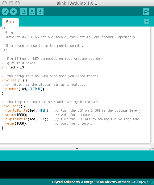


Once you select the "BLINK" sketch a window will pop up which will look like this picture. This is the code we will be using for our very first lesson. Thankfully someone came along and did the hard stuff for us. The beauty of using these prewritten codes is that we can learn alot by examples. For example you can fiddle around and change output pins for the led.  Another advantage of learning by examples is that if you notice on the sketches they have explanations of the codes alongside.
( // wait for a second )


So after you have this sketch in front of you the next step is to load it onto the Arduino.


STEP 3:  Connection Time


*** Connecting Arduino to Sketchbook ***


Start off by connecting one end to the Arduino and the free end connected to either your laptop
or you pc.

We are on our way to completing our first program. Hang in there. Once connected to your source ( laptop or pc) you will need to do acouple more things before we move on.
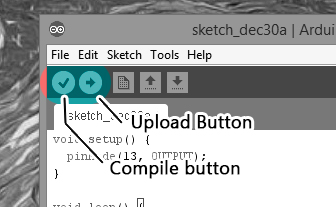


In order to transfer the "Blink" sketch onto the Arduino we firstly need to make sure that the code was been written properly and will work. One of the best things is how the programs has a built in checker that will verify that it makes sense and will run. If the coding isnt correct the sketch will be unable to load. If this happens you will recieve an error message detailing where you went wrong. We will cover common errors in a different post.


As you can see from the picture you have some options when it comes to finishing up on this project. First click on the "Compile" button. This runs a scan of your code and will make sure it is correct.
Next it will ask you to save. Save sure.

Lastly I would like you to click "Upload"

BAMMMM!


STEP 4: COMPLETE
Led "on"

EXTRAS:


If you are not done playing around you could also try playing around with the code. Maybe change the outputs? Add more leds? The photo on the left shows an led connected directly to the arduino.

Connect the led to Arduino by placing  "cathode" of the led ( - ) to the ground pin on Arduino. Place "anode"(+) to pin 13 on the Arduino. 


Sunday, 24 July 2016

WTF is ARDUINO?


Up intil a few years ago I had never pictured myself being as involved and interested in the world of electronics as I currently am, It all started from a late night Ebay stroll, 3 weeks later I was fixated. The Arduino world allows a total newb to jump on board and progress at a comfortable pace without overwhelming and confusing the user. The word "Arduino" can mean a few things, it can be meat as the board itself which is the hardware, it is also a software program which is how you program the hardware unit itself.


" Arduino is a hardware and software company, project, and user community that designs and manufactures computer open-source hardware, open-source software, and microcontroller-based kits for building digital devices and interactive objects that can sense and control physical devices." SOURCE


    This is called an " Arduino Uno" The Arduino Uno is a microcontroller board based on the ATmega328 (datasheet). It has 14 digital input/output pins (of which 6 can be used as PWM outputs), 6 analog inputs, a 16 MHz crystal oscillator, a USB connection, a power jack, an ICSP header, and a reset button.


Install the Arduino Software by simply pluging in the usb to your laptop or pc and await the installation popup.Once that is all done, Click the Arduino icon that you so wisely installed on your desktop for easy access.


   *** That's it ! Next its time to compose your first sketch ***

BEST PLACE 4 GTA GLITCHES


*** GTA 5 ONLINE *** 


--Looking 4 Glitches?
--Wanna Mod?
--Hack?
--Be a BOSSSSS


If you are like me and are awesome then you will definitely appreciate this link http://www.se7ensins.com/forums/threads/next-gen-dupe-glitch.1533635/page-169


I have been playing GTA since the dawn of the "O.G GTA1" and from day one I have cheated and I have no intention of playing any differently. The site above leads to a gaming forum which I use religiously. They have made me millions and millions. As of today there is a glitch available to duplicate your cars and resell. I encourage ya'll to stop watching the lame youtube vids which promise you sharkcard after sharkcard and survey bullshit things and seriously check these guys out.


Not only do they provide all platforms for cheats/ glitches/ walkthroughs but the members are on top of there A game and will gladly help ya out. I cannot say enough good things about this site.  

My advice is bookmark the shit outta the site and check back on the reg.

Wednesday, 20 July 2016

LED LESSON #1


In this quick lesson we will go over a very simple hook up in order to make an LED of your choice shed some light. In order to do this we will need to gather a few key elements in order to get this project off the ground. Leds can be used for anything and everything, they are perfect to add accents and lighting to your home, car or anywhere else. Nowadays people have shifted focus on using led strip lighting which offers easy installation as well as being easy to control. By following this walkthrough you should be able to understand the setup as well as the concept, so get ready and keep reading. 


STEP 1: Gather your gear
For this project you will need:
- L.E.D  ( Light emitting diode )
- 220 ohm resistor
- Breadboard
- jumper wires


Light Emitting Diode (L.E.D)
                                   LED

When placing the led onto the breadboard you need to know the orientation of the led itself. Take a look at the led description and get familiar with the different functions. The led in this case has two legs. The longer leg is called an "Anode" this leg is defined as positive (+). This is generally connected to the positive power supply. The shorter leg called an "Cathode" is defined as being the negative pin, which is connected to the ground through a resistor which we will discuss next.


Resistor

Resistors can be used in many different ways, they are mainly responsible for protecting components from being damaged such as in leds. They are the dams of electricity, different resistors can allow different flows to pass through. Resistors can split voltage between parts of a circuit as well as  control delays. Most resistors nowadays are carbon. Resistors have values assigned which are rated by the colours on them. The colours used are : black, brown, red, orange, yellow, green, blue,purple, gray, and white. The colours represent a different number. Black = 0 Brown= 1 all the way to White = 9.   Remember these numbers you will need to learn which applies to which.


STEP 2: Connections


First things first connect your power supply. I chose as always my own created "PSU"  Connect 5v to positive rail on the breadboard (red +) and ground will be connected to the blue breadboard rail (ground). Next insert the led (colour of your choice) into the breadboard as shown in the picture. For more information on how to use a breadboard you can check out my walk through which you will find in my project listings. Place "Anode" in one opening and "Cathode" in its own hole.


Now that the led and the power supply are connected we now move onto connecting the resistor. To do this we need to place the resistor with one end connected to the same rail as the cathode of the led. The other end of the resistor is in its own hole as well. Now place your jumper wires.


Connect the resistor with your jumper wire. One end of the jumper wire will be connected to the cathode end with the other end connected to the ground rail of the breadboard. Now we need power.


To do this we connect another jumper. This wire is connected to the anode of the led. This wire now gets connected to the red rail which will provide the 5v power needed to run the led.


Beautiful eh, if everything went smoothly then you should be sitting back relaxing and enjoying your progress. Some common issues if you cannot make light would be:

-LED is installed backwards
-improper power supply
-dead led